|
#2
29th December 2016, 06:16 PM
| |||
| |||
| Re: BPUT DCT New syllabus
As you are asking for BPUT DCT New syllabus, so on your demand I am providing same for you : PCEC 4305 DIGITAL COMMUNICATION TECHNIQUE (3-0-0) Module - I (12 hours) Sampling Theorem, Signal Reconstruction from uniform samples, Practical issues in signal sampling and reconstruction, Maximum Information Rate, Non-ideal practical sampling analysis, Some applications of sampling theorem (Ref Text Book 2: Chapter 6.1) Digital Representation of Analog Signal - Quantizatio n of Signals, Quantization error, PCM, Electrical representation of binary digits, PCM System, Companding, Certain issues in Digital transmission: Line coding, scrambling, T1Digital System, Multiplexing T1 lines – The T2, T3 and T4 lines. Differential PCM: Linear predicted design, Delta Modulation, Adaptive Delta Modulation (Ref Text Book 1: Chapter 5.4, 5.5 and 5.6) Module - II (14 hours) Digital Modulation Technique: G eneration, Transmission, Rec eption, Spectrum and Geometrical Repres entation in the Signal Space of BPSK, DPSK, QPSK, QASK, M-ary PSK, BFSK, M-ary FSK, and Minimum Shifting Keying (MSK). (Ref Text Book 1: Chapter 6) Noise in PCM and DM: Calculation of Quantization Noise, Output Signal Po wer, and the Thermal Noise. Output SNR in PCM, Quantization noise in Delta Modulation, output sig nal power, output SNR, Comparison with PCM and DM (Ref Text Book 1: Chapter 12.1 -12.3) Module - III (16 hours) Principle of Digital Data Transmission: Digital Communication Systems – Source, Line coder, Mult iplexer, Regenerative repeater;Line Coding: PSD of various line codes, polar signaling, constructing a DC Nu ll in PSD by pulse shaping, On Off signaling, Bipolar signaling; Pulse shaping – ISI and effect, Nyquist first cr iterion for zero ISI; Scrambling, Digital receiver and regenerative repeaters; Equalizers, Timing extraction, Detection error, Eye Diagram (Ref Text Book 2: Chapter 7.1, 7. 2, 7.3.1, 7.3.2, 7.4, 7.5, 7.6) A base band signal Receiver, Peak signal to RMS noise output voltage ratio, probability of error, optimum threshold, optimum receiver for both base band and pass band: calculation of optimum filter transfer function, optimum filter realization using Matched filter, Probability error of the matched filter, optimum filter realization using correlator BPUT DCT New syllabus 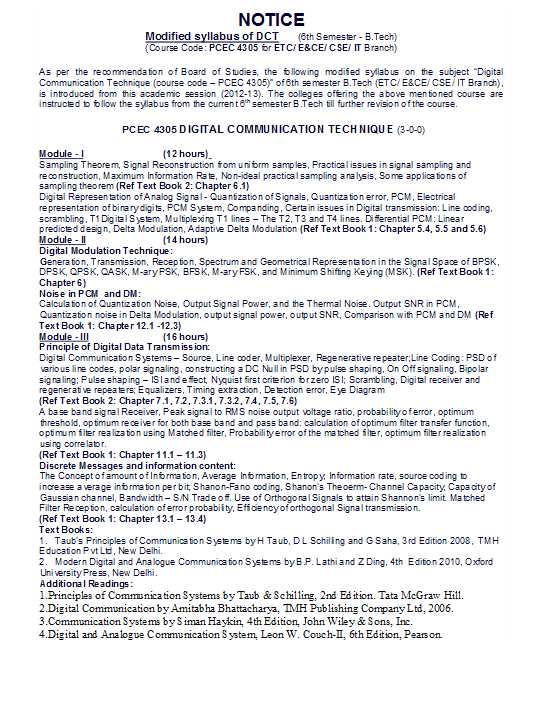 |