2023 2024 Student Forum > Management Forum > Main Forum

 
  #2  
31st July 2014, 02:37 PM
Super Moderator
 
Join Date: Apr 2013
Re: Info related to simple mobile Jammer circuit diagram and used

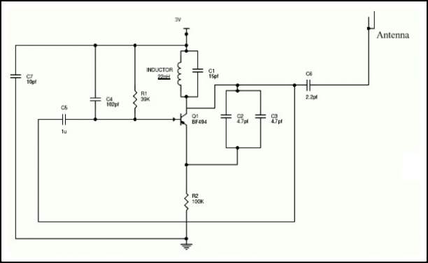
As you are looking for info related to simple mobile Jammer circuit diagram and used, so here i am providing an image which show Simple Mobile Jammer Circuit Diagram


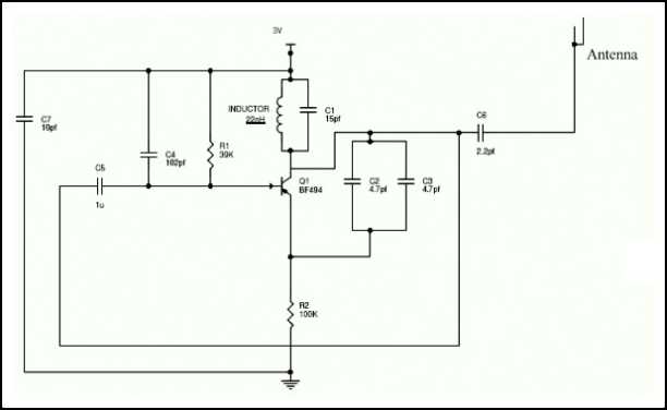
For understand any jammer circuit, remember one thing that there are three main important circuits and when they are combined together, the output of that circuit will work as a jammer. The three circuits are
RF amplifier.
Voltage controlled oscillator.
Tuning circuit.
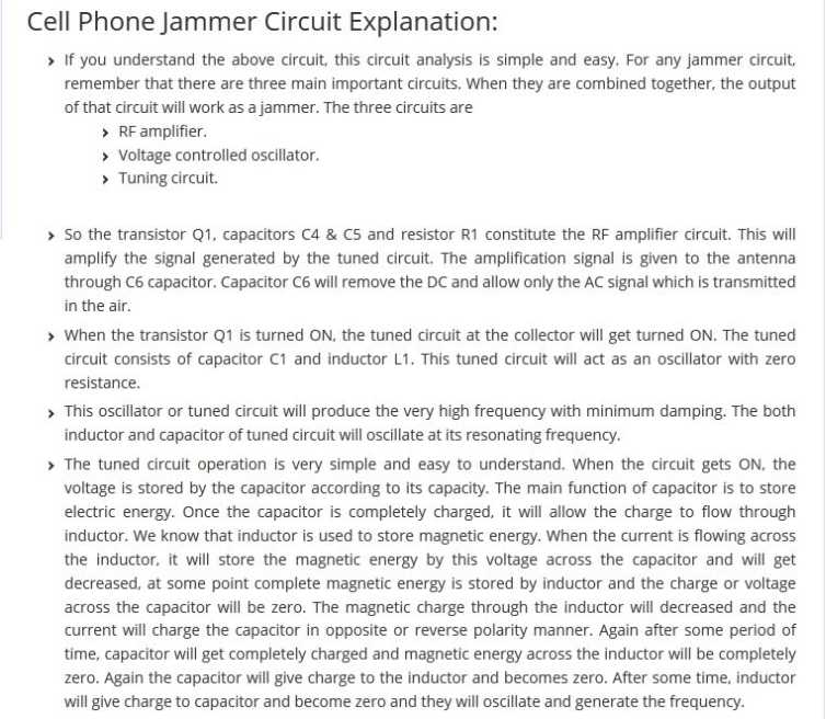

  #3  
16th March 2015, 05:25 PM
Unregistered
Guest
 
Re: Info related to simple mobile Jammer circuit diagram and used

I am searching for the simple mobile Jammer circuit diagram and used? Can you please provide me the simple mobile Jammer circuit diagram?
  #4  
16th March 2015, 06:04 PM
Super Moderator
 
Join Date: Mar 2013
Re: Info related to simple mobile Jammer circuit diagram and used

You are asking for the Simple Mobile Jammer Circuit Diagram. Here I am providing you the Simple Mobile Jammer Circuit Diagram. This is as follows:

Simple Mobile Jammer Circuit Diagram:


The Simple Mobile Jammer Circuit Diagram used a fm transistor for making this circuit.

Mobile phones are working in 450 MHz frequency .

the transmitter generate almost equal to 450 MHz frequency there for the mobile phone does not identify the original signal but the signal range is very week so this circuit working in only 100 m range

This circuit working in only 450 Mhz .

Do not give more than 3 V


Quick Reply
Your Username: Click here to log in

Message:
Options

Thread Tools Search this Thread


All times are GMT +5. The time now is 12:45 AM.


Powered by vBulletin® Version 3.8.11
Copyright ©2000 - 2024, vBulletin Solutions Inc.
SEO by vBSEO 3.6.0 PL2

1 2 3 4