|
#2
2nd August 2015, 05:09 PM
| |||
| |||
| Re: Anna University FM Lab Manual
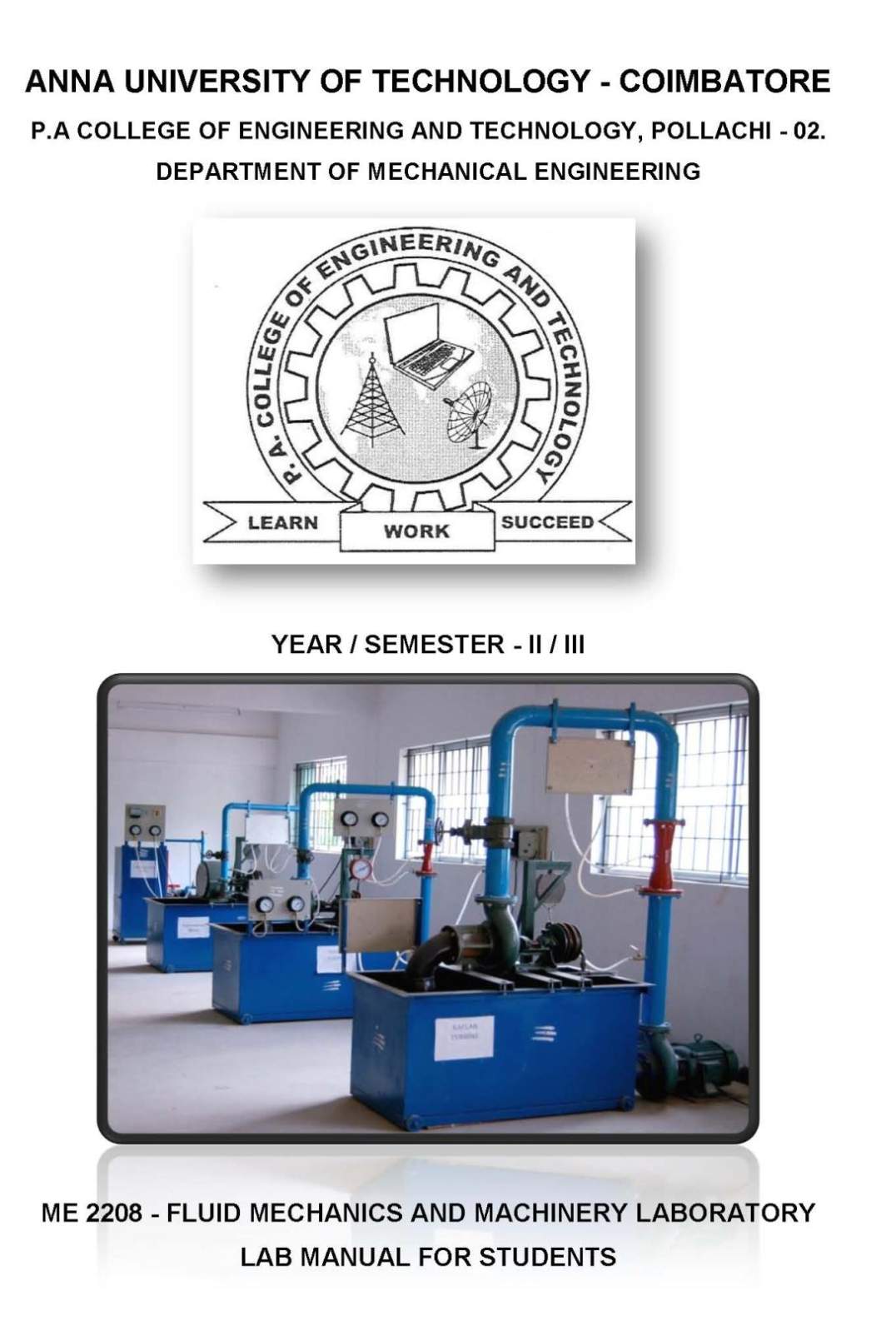
As you want to get the details of Fluid Mechanics and Machinery Laboratory Lab Manual of Anna University so here is the information of the same for you: FLUID MECHANICS AND MACHINERY LAB: 1. Determination of the coefficient of discharge of given Orifice meter. 2. Determination of the coefficient of discharge of given Venturi meter. 3. Calculation of the rate of flow using Rota meter. 4. Determination of friction factor of given set of pipes. 5. Conducting experiments and drawing the characteristics curves of centrifugal pump. 6. Conducting experiments and drawing the characteristics curves of reciprocating pump. 7. Conducting experiments and drawing the characteristics curves of Gear pump. 8. Conducting experiments and drawing the characteristics curves of Pelton wheel. 9. Conducting experiments and drawing the characteristics curves of Francis turbine. 10. Conducting experiments and drawing the characteristics curves of Kaplan turbine. DETERMINATION OF THE CO-EFFICIENT OF DISCHARGE OF GIVEN ORIFICE METER: AIM: To determine the co-efficient discharge through orifice meter APPARATUS REQUIRED: 1. Orifice meter 2. Differential U tube 3. Collecting tank 4. Stop watch 5. Scale DESCRIPTION: Orifice meter has two sections. First one is of area a1, and second one of area a2, it does not have throat like venturimeter but a small holes on a plate fixed along the diameter of pipe. The mercury level should not fluctuate because it would come out of manometer. PROCEDURE: 1. The pipe is selected for doing experiments 2. The motor is switched on, as a result water will flow 3. According to the flow, the mercury level fluctuates in the U-tube manometer 4. The reading of H1 and H2 are noted 5. The time taken for 10 cm rise of water in the collecting tank is noted 6. The experiment is repeated for various flow in the same pipe 7. The co-efficient of discharge is calculated DETERMINATION OF THE CO EFFICIENT OF DISCHARGE OF GIVEN VENTURIMETER : AIM: To determine the coefficient of discharge for liquid flowing through venturimeter APPARATUS REQUIRED: 1. Venturimeter 2. Stop watch 3. Collecting tank 4. Differential U-tube 5. Manometer 6. Scale DESCRIPTION: Venturimeter has two sections. One divergent area and the other throat area. The former is represented as a 1 and the later is a 2 water or any other liquid flows through the Venturimeter and it passes to the throat area the value of discharge is same at a 1 and a 2 . PROCEDURE: 1. The pipe is selected for doing experiments 2. The motor is switched on, as a result water will flow 3. According to the flow, the mercury level fluctuates in the U-tube manometer 4. The reading of H1 and H2 are noted 5. The time taken for 10 cm rise of water in the collecting tank is noted 6. The experiment is repeated for various flow in the same pipe 7. The co-efficient of discharge is calculated CALCULATION OF THE RATE OF FLOW USING ROTOMETER: AIM: To determine the percentage error in Rotometer with the actual flow rate APPARATUS REQUIRED: 1. Rotometer setup 2. Measuring scale 3. Stopwatch. PROCEDURE: 1. Switch on the motor and the delivery valve is opened 2. Adjust the delivery valve to control the rate in the pipe 3. Set the flow rate in the Rotometer, for example say 50 liters per minute 4. Note down the time taken for 10 cm rise in collecting tank 5. Repeat the experiment for different set of Rotometer readings 6. Tabular column is drawn and readings are noted 7. Graph is drawn by plotting Rotometer reading Vs percentage error of the Rotometer DETERMINATION OF FRICTION FACTOR OF GIVEN SET OF PIPES: AIM: To find the friction ‘f’ for the given pipe. APPARATUS REQUIRED: 1. A pipe provided with inlet and outlet and pressure tapping 2. Differential u-tube manometer 3. Collecting tank with piezometer 4. Stopwatch 5. Scale DESCRIPTION: When liquid flows through a pipeline it is subjected to frictional resistance. The frictional resistance depends upon the roughness of the pipe. More the roughness of the pipe will be more the frictional resistance. The loss of head between selected lengths of the pipe is observed PROCEDURE: 1. The diameter of the pipe is measured and the internal dimensions of the collecting tank and the length of the pipe line is measured 2. Keeping the outlet valve closed and the inlet valve opened 3. The outlet valve is slightly opened and the manometer head on the limbs h1 and h2 are noted 4. The above procedure is repeated by gradually increasing the flow rate and then the corresponding readings are noted   For more detailed information I am uploading a PDF file which is free to download: Contact Details: Anna University MIT Road, Chromepet Kotturpuram Chennai, Tamil Nadu 600025 India Map Location: [MAP]Anna University Kotturpuram Chennai[/MAP] |